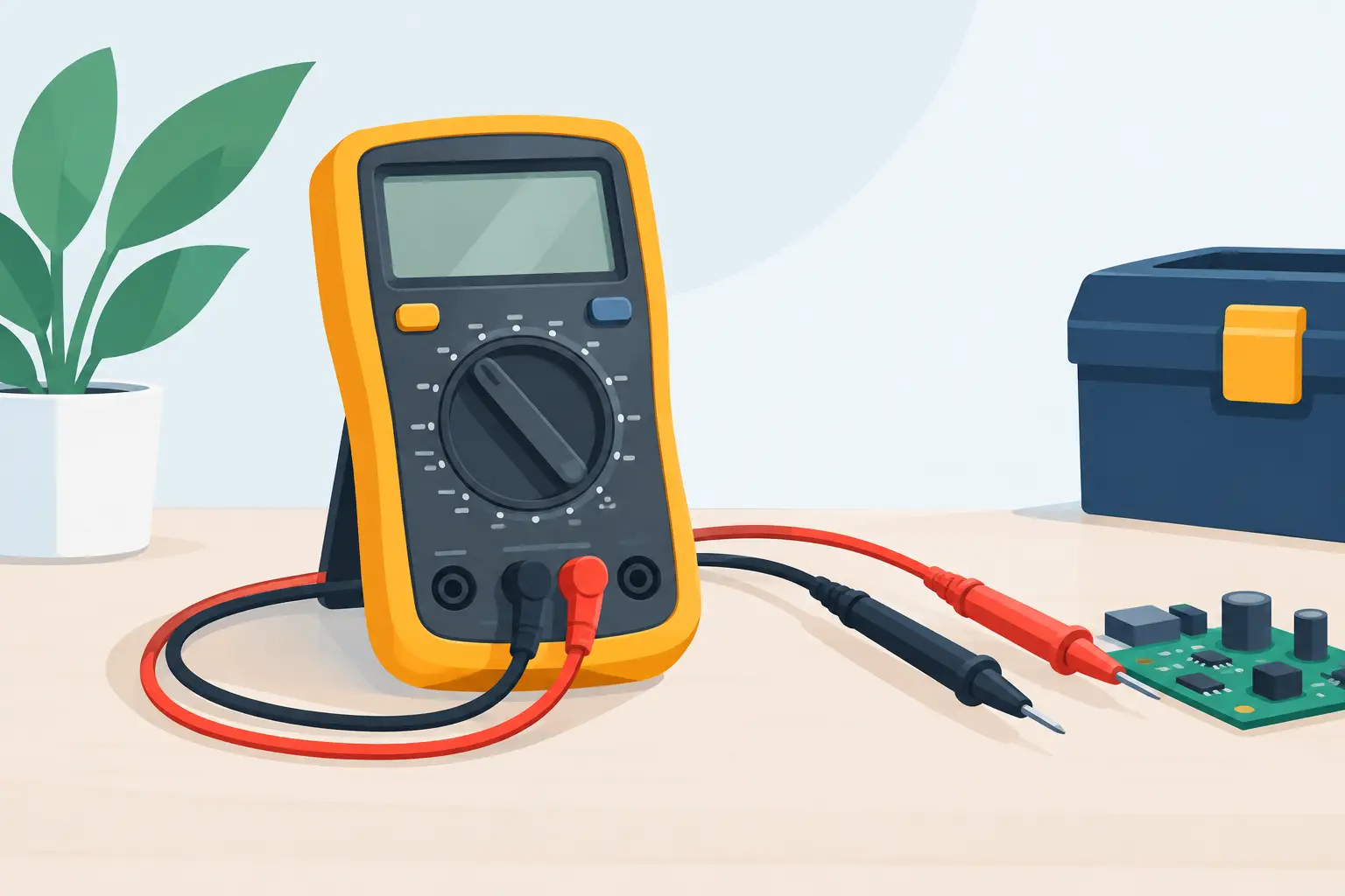
A multimeter can tell you why a battery-powered tool will not start, whether a fuse has failed, or if a wall outlet has power. Learning how to use a multimeter starts with one rule: choose the right setting before the probes touch anything. A few seconds of setup prevents blown fuses in the meter, damaged electronics, and unsafe readings.
For everyday repairs, an affordable digital multimeter is usually the practical choice. It gives a clear numerical readout and covers the tests most homeowners, makers, technicians, and garage DIYers need: voltage, resistance, continuity, and current.
Know Your Multimeter Before You Test
Most digital multimeters have a display, a rotary dial, and two or three probe ports. The black probe almost always goes into the port marked COM, meaning common. The red probe normally goes into the port marked VΩ or VΩmA. That port is used for voltage, resistance, continuity, diode testing, and low current measurements.
Many meters also have a separate high-current port labeled 10A, 20A, or similar. Use it only when measuring current and only when the meter and circuit are rated for that test. Leaving the red lead in this port is one of the most common beginner mistakes. If you then try to measure voltage across a battery or outlet, you can create a short circuit.
The dial symbols are straightforward once you know the basics:
- V with a straight line and dotted line means DC voltage, used for batteries, vehicles, USB power, and most electronics.
- V with a wavy line means AC voltage, used for household outlets and many appliances.
- Ω means resistance.
- A sound-wave or diode-like symbol usually means continuity.
- A or mA means current.
Some meters are manual-ranging, so you select a maximum range such as 20V or 200V. Start above the voltage you expect, then step down if needed for a more precise reading. Auto-ranging models choose the range for you, which is faster for general use.
Safety First When Using a Multimeter
A multimeter is useful because it measures energized circuits, but that is also where the risk is. Do not use cracked probes, damaged leads, or a meter with a broken case. Check the printed voltage and measurement category ratings on the meter before working near household power. A meter rated for basic low-voltage electronics is not automatically suitable for a service panel or high-energy circuit.
When checking AC outlets, hold the probes behind their finger guards. Keep your fingers dry, avoid metal jewelry, and do not let the metal probe tips touch each other while they are in an energized outlet. Work with one hand when practical, especially around higher-voltage circuits, and stand on a dry surface.
A standard US outlet should read roughly 120V AC between the narrow slot and wide slot. Voltage can vary slightly. If a reading is unexpected, do not assume the circuit is safe or that the meter is wrong. Stop and investigate with the power off, or call a qualified electrician for wiring, breaker-panel, or repeated tripping issues.
How to Use a Multimeter to Check Voltage
Voltage testing is the measurement most people use first. It answers a simple question: is electrical power present, and is it close to the expected level?
Test a Battery
Insert the black lead into COM and the red lead into VΩ. Set the dial to DC voltage. For a 1.5V AA or AAA battery, choose a range just above 1.5V, such as 2V or 20V. Touch the black probe to the negative battery terminal and the red probe to the positive terminal.
A fresh alkaline AA battery often reads around 1.5V to 1.6V with no load. A reading near or below 1.2V can indicate a weak battery, though the real test depends on the device and how much current it draws. Rechargeable nickel-metal hydride batteries are different: about 1.2V when nominally charged is normal for their chemistry.
For a 9V battery, use a setting above 9V. For a car battery with the engine off, select DC voltage above 12V. A healthy, resting lead-acid car battery commonly measures around 12.6V. Much lower may point to a discharged battery, but battery condition, temperature, and charging history all matter.
Test a Wall Outlet
Set the meter to AC voltage and choose a range above 120V if it is manual-ranging. Put the black probe into the wide slot and the red probe into the narrow slot. The display should show approximately 120V.
To check whether the ground is present, measure between the narrow slot and the round ground opening. That should also be about 120V. Between the wide slot and ground, the reading should be close to zero. These readings can flag a concern, but they do not prove an outlet is wired correctly in every scenario. An outlet tester or an electrician may be the better next step if you suspect a wiring fault.
Check Continuity Before Replacing Parts
Continuity mode is one of the quickest ways to find a broken fuse, wire, switch, or connection. The meter beeps when there is a low-resistance path between the probes.
Always disconnect power before a continuity test. Remove batteries, unplug the device, and allow stored energy to dissipate. Then set the meter to continuity, touch the probes together, and confirm that it beeps or reads close to zero. This proves the leads and setting are working.
Touch the probes to opposite ends of a fuse. A good fuse generally beeps. If the display shows OL, 1, or no beep, the fuse is open and likely blown. Test a removed fuse when possible. Testing it while installed can produce misleading results because other components may create an alternate path.
You can use the same method on a loose extension cord. Check each blade on the plug against its matching slot on the female end. Each matching conductor should show continuity, while different conductors should not. If a cord is damaged, warm during use, or intermittently loses power, replacement is usually safer than a temporary repair.
Measure Resistance the Right Way
Resistance testing helps evaluate components such as resistors, heating elements, sensors, and switches. Set the dial to Ω, then place the probes across the component terminals.
The circuit must be powered off. More importantly, the component often needs to be isolated from the circuit for an accurate reading. Nearby components can change the measured value, so reading resistance directly on a circuit board may not tell the full story.
A display of OL usually means resistance is beyond the selected range or the circuit is open. A reading near zero means very low resistance. Neither result is automatically good or bad. A heating element is supposed to have some resistance, while an open fuse is not. Compare the result with the component specification or service information when available.
Use Current Mode Only When You Need It
Current measurement is different from voltage testing. To measure current, the meter must become part of the circuit, connected in series rather than placed across the power source. This is useful for diagnosing parasitic battery drain, checking a small motor, or confirming the draw of a low-voltage device, but it carries more risk of error.
Start by moving the red probe to the correct current port and selecting the highest current range. Open the circuit, then connect the meter so all current flows through it. Never place a meter set to amps directly across a battery, outlet, or power supply. That can blow the meter fuse or create a dangerous short.
For many home and electronics jobs, voltage and continuity tests provide the answer without measuring current. Use current mode when you understand the expected load and the meter's limits.
Common Readings That Cause Confusion
A negative DC voltage reading usually means the probes are reversed. The value itself may still be correct, just with opposite polarity. Swap the probes if you want a positive number.
An OL reading can mean an open circuit, a resistance value above the selected range, or probes that are not making contact. A reading that jumps around may come from loose probe contact, a weak meter battery, electrical noise, or an unstable circuit.
If the display stays at zero when you expect voltage, first verify the dial is on the correct AC or DC setting and that the red lead is in the VΩ port. Then test a known-good battery or outlet, using the correct safety precautions. This quick check separates a setup error from the problem you are trying to diagnose.
A dependable multimeter earns its place in a tool drawer because it replaces guesswork with a reading you can act on. Keep the probes in the right ports, start with the correct measurement mode, and stop when a circuit or reading falls outside your comfort level. The right tool, used carefully, can turn a stalled repair into a straightforward next step.