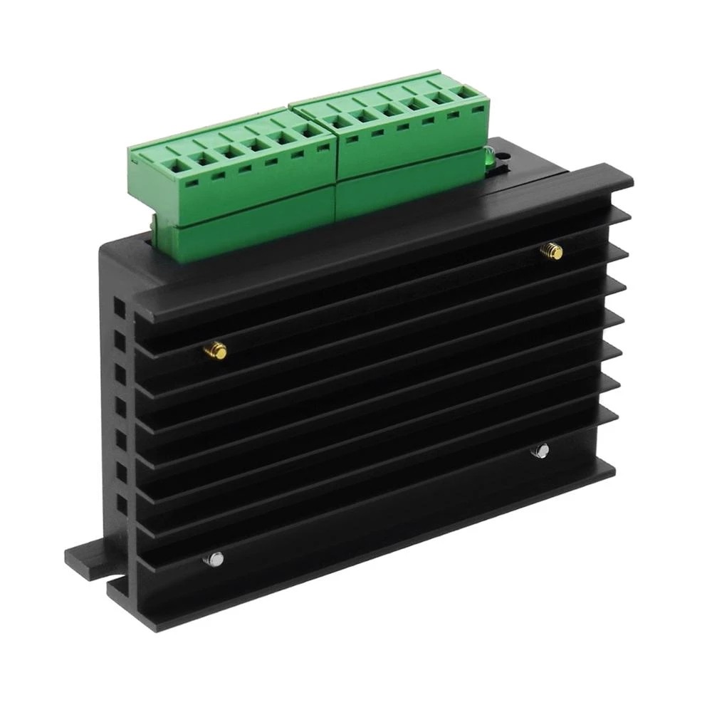
Subdivision Stepping Motor Driver Router Controller
0.0 · 0 reviewsor 4 interest-free payments of $2.00 with Klarna or Afterpay
Option: Black-1PCS
Bundle & save
Ships from our overseas warehouse — not from the US
Shipping calculated at checkout · International items 8–15 business days
30-day money-back guarantee
Product information: Signal input: ⑴CP+: Pulse signal input positive terminal. ⑵CP-: Pulse signal input negative terminal. ⑶DIR+: The positive terminal of the motor forward and reverse control. ⑷DIR-: The negative terminal of the motor positive and reverse control. ⑸EN+: The positive terminal of the motor offline control. ⑹EN-: The negative terminal of the motor offline control. Motor winding connection: ⑴A+: Connect the A+ phase of the motor winding. ⑵A-: Connect the motor winding A-phase. ⑶B+: Connect the B+ phase of the motor winding. ⑷B-: Connect the B-phase of the motor winding. Connection of working voltage: ⑴VCC: DC power supply is positive (note: 10V <VCC <42V). ⑵GND: DC power supply negative. Signal input terminal optocoupler isolation connection method: There are two connection methods for the input signal interface: users can adopt common anode connection or common cathode connection according to their needs. 1. Common anode connection: connect CP+, DIR+, EN+ to the power supply of the control system respectively. If the power supply is +5V, it can be connected directly. If the power supply is greater than +5V, an external current-limiting resistor R must be added., Guarantee to provide 8-15mA drive current to the internal optical coupling of the driver. The pulse input signal is connected through CP-; at this time, DIR- and EN- are valid at low level. 2. Common cathode connection: connect CP-, DIR-, EN- to the ground terminal of the control system (SGND, isolated from the power ground); +5V pulse input signal is added through CP+; at this time, DIR+, EN+ are in Active high. The connection method of the current-limiting resistor R is the same as the common anode connection. Note: The EN terminal can be left unconnected. When EN is valid, the motor rotor is in a free state (off-line state). At this time, you can manually rotate the motor shaft to make adjustments that suit you. After the manual adjustment is completed, set EN to an invalid state to continue automatic control. Packing list: Motor Driver*1 Product Image:
- Ships with tracking
- 30-day money-back guarantee
Recently viewed
Live reviews